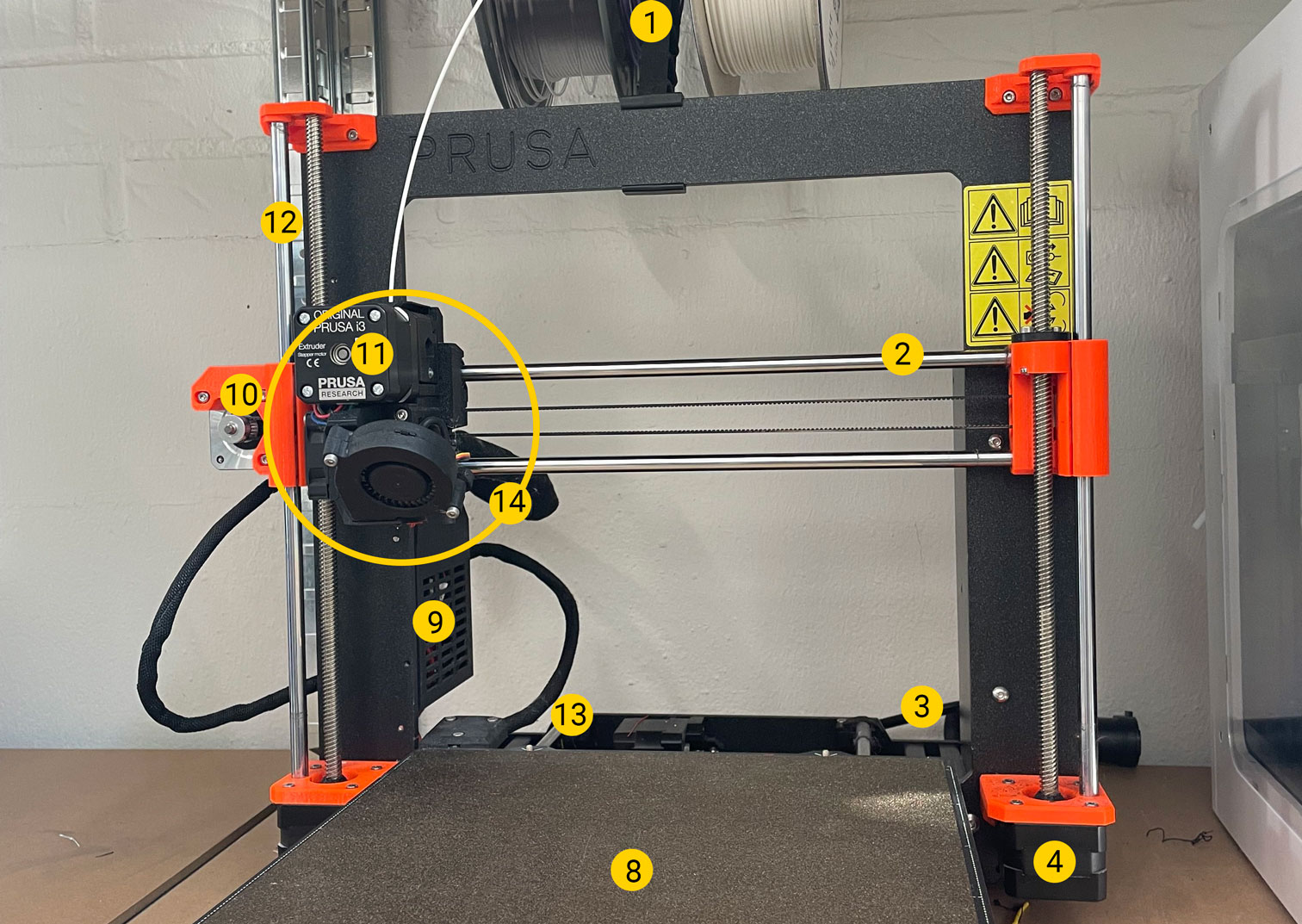
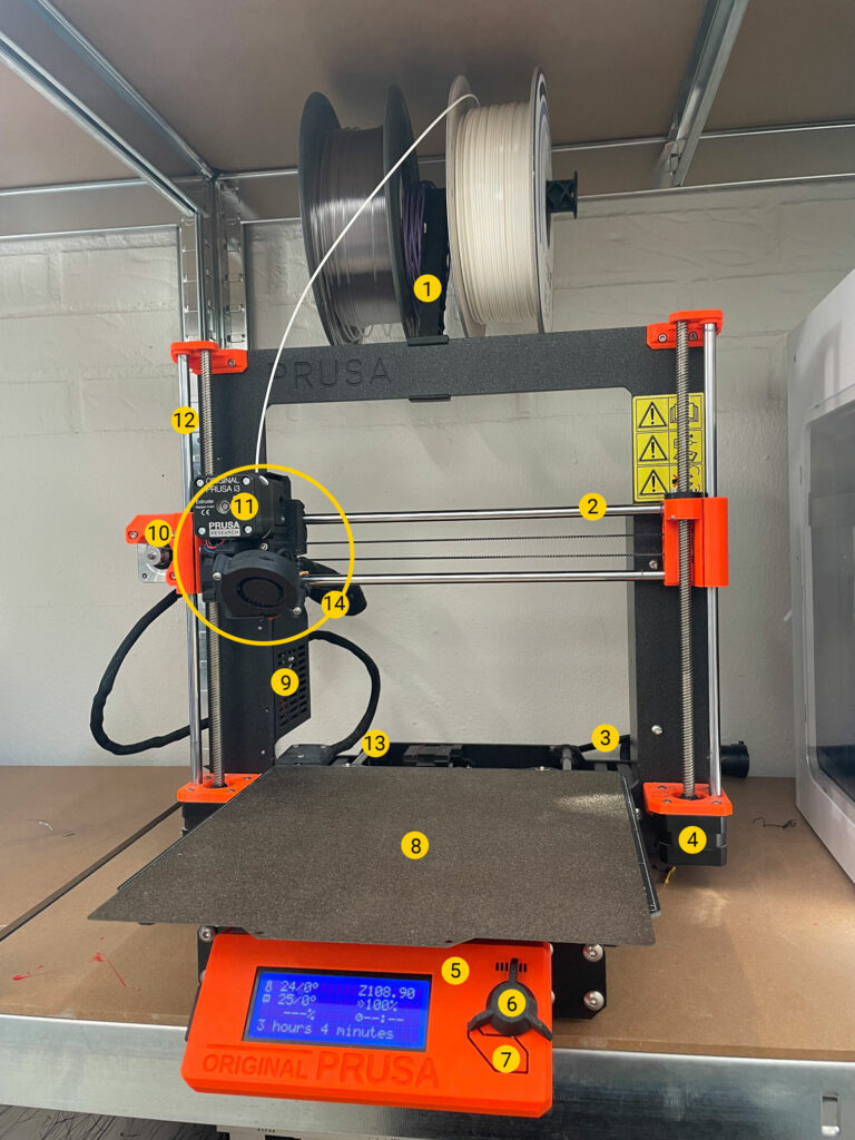
For those new to the world of 3D printing, understanding the various components of a 3D printer can be a bit daunting. This guide provides an overview of the key parts that make up a typical FDM (Fused Deposition Modeling) 3D printer, helping you familiarize yourself with its essential components and their functions. We take a Prusa i3 MK3 as an example, but the parts are essentially the same for other FDM 3D printers.
- Filament holder
Designed to provide smooth and consistent filament feeding for printing. - X axis
The left and right motions move along the X-axis. - Power cable
It is the power supply that provides all of the power necessary for the printer to function. - Z motors
Stepper motors that drives the movement of the print bed in the Z-axis direction through the Z-axis synchronous belt. - Controller
This is the central unit of the printer, often referred to as its “brain”. It’s typically where the control interface is located and where all the components are connected. 3D printers can operate various types of firmware, with Marling being one of the most widely used options. - Main control button
When you want to confirm something, you press this. - Reset button
If you want to reboot your printer, use this. The printer will immediately stop. - Print bed
This is the surface where the print will be built on. It can be made of many kinds of materials. PEI is a common material that can be added to the print bed that helps the print stick to the bed. - Control unit
The controller, or mainboard is the brain of the 3D printer, coordinating all its functions. It interprets G-code to manage the movement of motors, temperature regulation, and sensor inputs. This ensures precise printing and the overall operation of the printer. - X motor
Stepper motor that drives the movement of the print bed in the X-axis direction through the X-axis. - Print head motor
Typically a stepper motor, that is responsible for moving the print head along the X and Y axes. This precise movement allows the printer to accurately deposit filament layer by layer. The motor ensures that the print head follows the paths specified in the G-code for each layer of the print. - Z axis
The forward and backward motions move along the Z-axis. - Y axis
The up and down motions move along the Y-axis. - Hot end
The hot end assembly is the part of the printer where the plastic filament melts, allowing it to be deposited onto the print surface. It consists of several components. These are detailed in the next section.
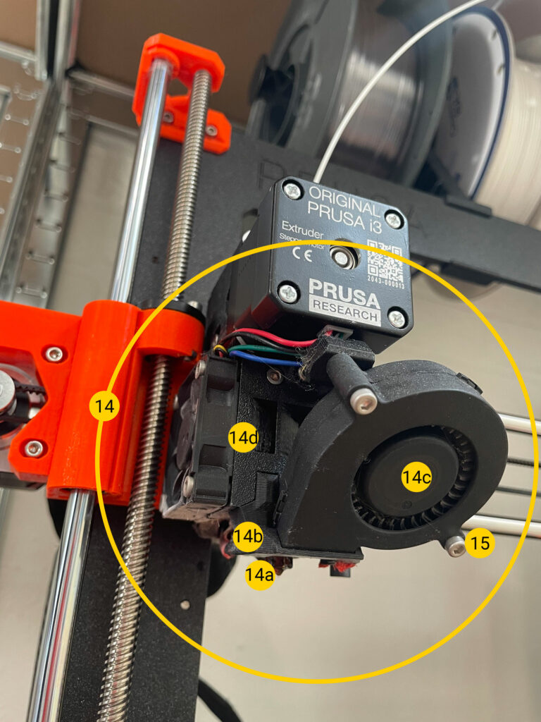
14 a. Nozzle
The nozzle heats up to melt the filament and is attached to the heater block. Nozzles come in various sizes, ranging from as small as 0.1 mm to 2 mm or more, depending on the application. The standard size is 0.4 mm, but nozzles can be swapped out for different sizes as needed.
14 b. Heater block
The heater block houses the heater cartridge and may include insulation to minimize heat fluctuations. This insulation helps maintain a consistent temperature.
14 c. Cooling fan
The cooling fan helps regulate the temperature of the heat break, preventing overheating.
Part cooling fan
The part cooling fan rapidly cools the freshly extruded material. While not all printer have this fan, and it’s not always necessary, its use depends on the type of filament. For instance, PLA filament benefits from rapid cooling to maintain shape, whereas ABS filament can warp if cooled too quickly.
14 d. Extruder
The extruder is responsible for feeding the filament into the nozzle for printing. It involves a motor with a gear that rotates, gradually pushing the filament into the hot end. Extruders generally come in two styles: Bowden or direct drive. This model is direct drive.
15. Sensor
Prusa MK3 uses a Pinda Probe for adjustment. It is a silver cylinder with a plastic end at the bottom, and a screw thread on the body, located to the right of the extruder. The Pinda is an inductive sensor, and it senses metal and magnets. It has a short sense distance, and when set up as described in the assembly manual, it senses the build plate (or the print bed tracks during XYZ calibration).
End stops/limit switches
The printer that has no sensors, have stop/limit switches instead. These define the home positions for each axis of the printer. During the homing process, the printer moves each axis toward these end stops. When an axis reaches its corresponding end stop, it stops, signaling to the printer that the axis is at its home position.
Additional parts
These parts are not required but they are becoming more common.
Auto level sensor
Auto level sensors, though optional, are becoming increasingly common. They come in various forms and can sometimes replace the Z-axis end stop. This sensor measures the high and low points on the print bed, allowing the printer to adjust for any unevenness and print evenly across the surface. This feature can eliminate the need for manual bed leveling.
Filament sensor
This device detects when the filament runs out and pauses the print, preventing printing errors due to a lack of material.
I hope this guide helped you to demystify your machine. Understanding the components of a 3D printer empowers you to troubleshoot, maintain, and optimize your printer. Whether you are a hobbyist or a professional, knowing the anatomy of your FDM printer is key to unlocking its full potential and achieving the best printing results.
Happy printing!✌️
Start printing with REALvision Online