Infill density basically defines the amount of filament that is put inside your object. The more infill the stronger object, but also a larger filament use, increased weight, and longer print time. Now I would like to show you 3 examples of how you should apply the different infill densities.
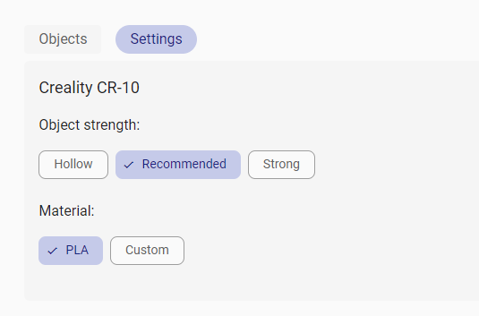
There are three types of infill density options – so-called object strengths – available in REALvision Online: Hollow, Recommended and Strong. The main difference among them is the infill density percentage. The layer height is 0.2 mm for all options with crossed infill type and shell thickness of 1 mm except for the Strong option where the shell thickness is 2 mm.
Hollow infill density
The infill density with the Hollow option is 0%. This means that you will have an object that relies only on the outer layers (the shell). This can be beneficial, for prints that are not functional. For example, if you would like to make a display model, a prototype, and don’t want to use much time and filament in the testing process.
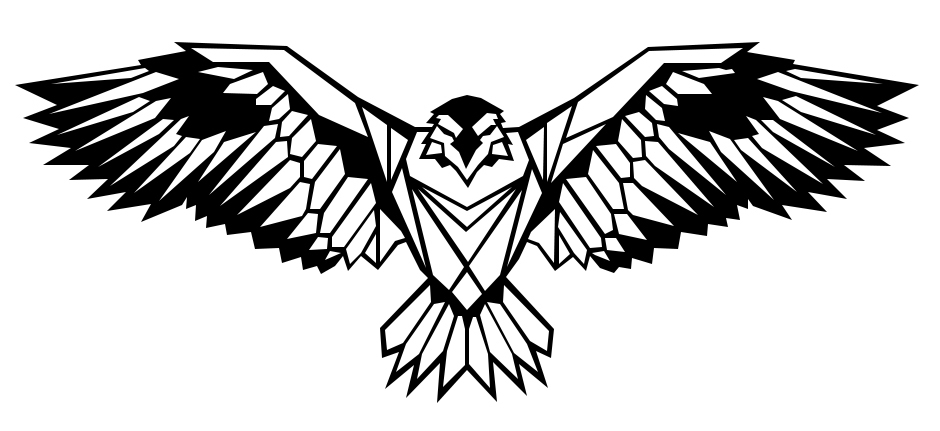
Wall decorations are a good example of this. They serve as decoration, don’t have to withstand significant force and as they have to be mounted on the wall it is an advantage if they are light.
Recommended infill density
The infill density with the Recommended option is 15%. This is the usual approach for prints that work for most of the prints that do not require specific hollowness or strength. Perfect for functional parts which will undergo a moderate force. This infill density provides nearly the same strength as a solid part in less time and at a reduced cost.
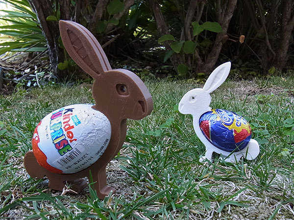
These Easter egg holder bunnies are a good example. They are fun prints that have some function with light force but rather serve decorative purposes.
Strong infill density
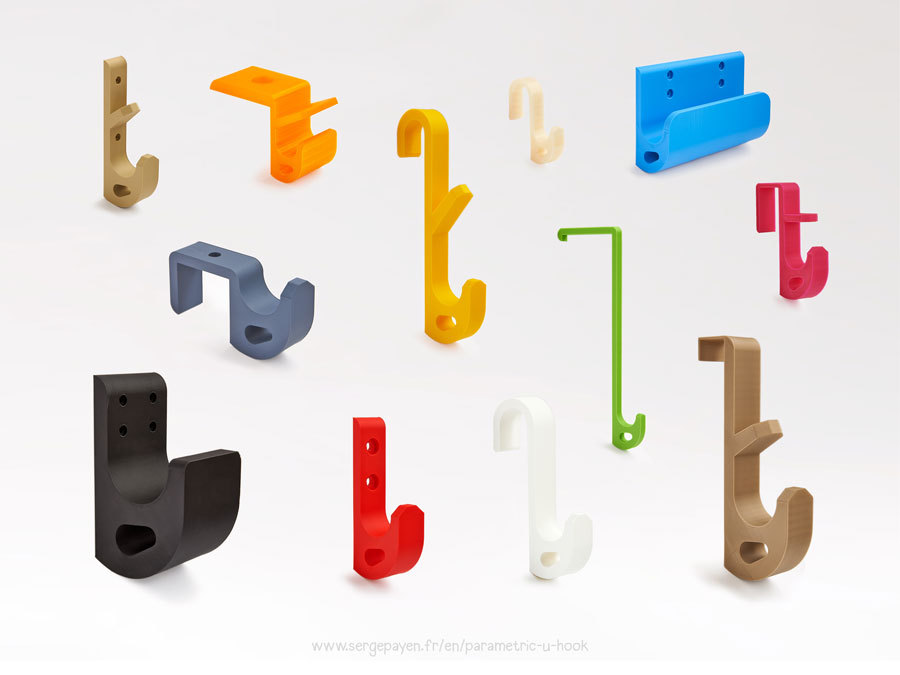
The infill density with the Strong option is 30%. Strong infill density results in a very strong object. This should be used to print parts when strength is a priority, the object needs to withstand significant force. For example for printing this customizable hook. This is an easily printable universal and very strong parametric hook.
The designer says the hook supports a weight of almost 50 kg, printed in PLA, with 0.2 mm layer height, and 20% infill.
The only thing to remember is that you will also have increased weight, filament usage, and printing time with this strong print option.
I hope you now have a good feeling about when to use the different object strengths to get great 3D prints without wasting time and material. I wish you happy printing!
Good to know – General terms related to 3d printing
| 3D printers If you have bought a cheap desktop 3D printer like an FDM printer from Creality but you are not satisfied with the quality of the Creality slicer, then you are not the only one. Historically those printers were sold as kits for 3D printer enthusiasts developing 3D printers themselves such as the RepRap project. Today most 3D printer enthusiasts just want to spend time on printing and not on fixing the 3D printer. This is why slicing and the slicing software is a big part of the success of 3D printing. |
| Filament In Fused Filament Deposition technology, also known as Fused Filament Fabrication, the spool of filament is the material used to build the 3D part by melting the plastic out of the nozzle of the 3D printer. The printer extrudes the filament line by line, layer by layer, by increasing the z-axis, and will build the 3D printed part. |
| STL files STL files are three-dimensional geometries CAD files based on a list of triangles defining the wireframe or the outside shell of the 3D object geometry. There are two types of STL files: they can be ASCII or Binary. The binary STL file format is more size optimized (takes less byte size) while the Ascii STL file format is humanly readable (can be opened in a text editor) and defines the tessellation (list of triangles creating the 3D polygon). To define a triangle the STL file format is a list of triangles made from 3 vertex or 3D vectors. Of course, there are a lot of triangles and they are fairly small so those triangles next to each other define the meshes of your STL 3D print file. |
| CAD / 3D CAD softwares CAD stands for Computer-Aided Design, it is the software part of CAD-CAM solution where you create your 3D designs or more precisely create your 3D models (actual 3D geometries). You can use beginner CAD software like Tinkercad, Google Sketchup, or more advanced CAD software like Autodesk Inventor, using Solidworks, 3DS, Autocad, or even parametric CAD design software like Openscad (script-based CAD software). All CAD software can export a CAD file under different file formats, but without a doubt, the most popular one is the STL file format. |
| GCODE files Gcode files are the files used for 3D printing. There are two types of Gcode files they can be ASCII or Binary, the Ascii files have a bigger file size and are humanly readable, while binary files are not humanly readable. You can easily preview an Ascii Gcode instruction by opening it in a text editor. The file extension or file format is .gcode and is generated from a CAM software usually named a slicer. |
| CAM / Slicer 3D printing software A CAM software in 3D printing is most commonly called a slicer. Slicers are used to create Gcode files. For beginner and intermediate users, you can use online slicers like the online slicer REALvision online; or for expert users, you can use slicers like REALvision Pro, Cura, Ultimaker Cura, Simplify 3D, Creality slicer or Slic3r. A slicer lets you manipulate the STL and then takes a planar cut or cross-section cut of your STL 3D design and automatically generates the movement instruction of your 3D printer (the toolpath) as well as all the repositioning and print strategy of the 3D printer. The filename generated from the slicer or CAM is called a GCODE file and the file format is a .gcode. You can usually simulate the 3D print result by looking at a slicer 3D viewer. |
| A CAD-CAM solution is a combination of creating a 3D design, preparing the manufacturing of the part and ultimately automatically manufacturing the party using an FDM 3D printer or a 3D printing service (like Shapeways, 3Dwarehouse |
| 3D printing Services To print 3D files you can use printing 3D files services such as Shapeways or Materialise. You can upload your STL files and they will ship your 3d prints to your home for a fee. |
| Marketplace If you are not confident in designing your STL 3D files yourself you can download a lot of STL files for free on websites like Thingiverse or Cult 3D where there are thousands of free STL files to choose from. |